[新しいコレクション] ic 2399 circuit diagram 933738-Ic 2399 circuit diagram
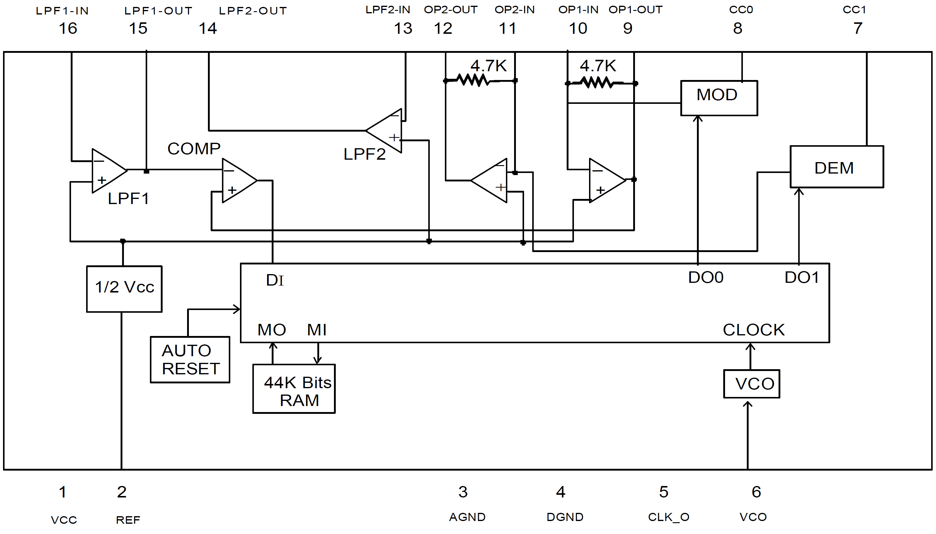
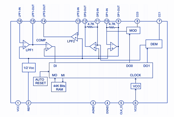
2 PT2399 Internal Circuit The main problem with the PT2399 is to understand the internal circuit, the Princetown datasheet is not very helpful This block diagram could be redrawn in a more logical and simpler way This chip effectively includes 6 internal opamps ( that the designer can use) and a power supply subsystemPT2399 input signal amplitude is about 3Vpp signal level higher than this range will be limiting In the above diagram, the change of pin 15, pin 16 of the resistive and capacitive components, you can change the input frequency response;Nov 30, 12 · Circuit Diagram, Electronic Components November 30, 12 The PT2399 is a single chip echo processor IC utilizing CMOS technology Which accept analog audio input signal, a high sample rate ADC transfer the analog signal into a bit stream then storage to internal 44Kbit RAM, after processing the bit stream will demodulate by DAC and lowpass

Echo Effect Preamp Board For Microphone With Pt2399 Ic Diy Hindi Electro India Youtube
Ic 2399 circuit diagram
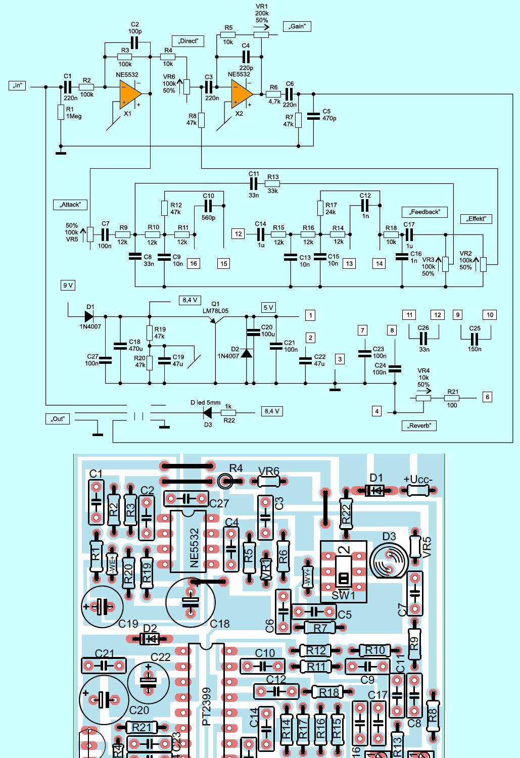
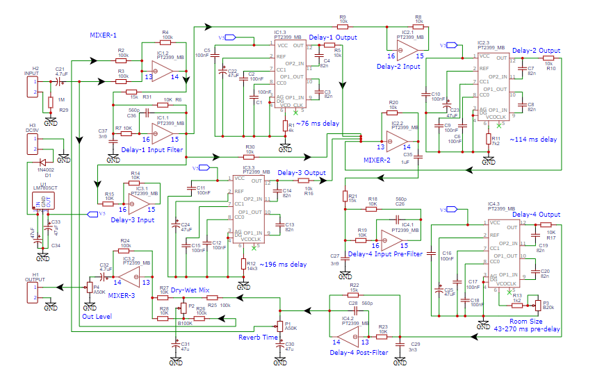
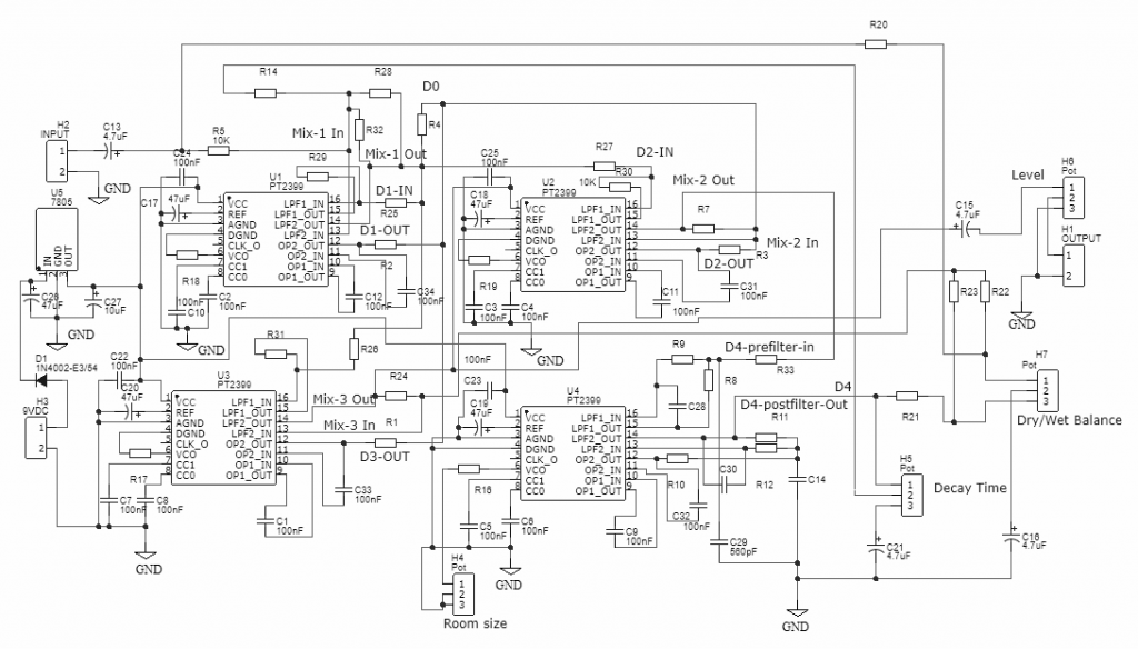
Ic 2399 circuit diagram-Jul 02, 19 · The PT2399 is an Echo Processor IC that is commonly used to provide digital delay in audio circuits The IC takes in analog audio input and converts it into digital stream of bits to add a digital delay to it This audio delayed audio signal is then provided as outputThe Complete Circuit's Schematic Diagram A testing in digital domain (using Deepstomp platform) has shown that the basic block diagram of the circuit works fine For the actual hardware, here is the schematic diagram of the reverb pedal circuit (Figure 6) It has four controls decay time, room size, dry/wet balance, and the output level


Build An Experimental Echo Pedal Make
Jul 08, 14 · The above shown electronic design capable of producing delay up to 24 hours so that it can be employed in numerous ways such as alarms, device activators etc This diagram demonstrates how to build a 24 hours timer circuit it around an IC 4060 Let us move into working explanation of this circuitOct 29, 15 · Patrick Kelly says October 29, 15 at 400 pm Hey Bat, According to the schematic, pin 3 is the input from the battery and the dc jack (9v in), pin 2 is the ground connection, and pin 1 is 5v out to the circuit It sounds like you may have a short somewhere in your circuit, or maybe the dc jack isn't wired right?Jun 05, 21 · Delay circuit page 6 meter counter circuits next gr The pt2399 is an echo processor ic that is commonly used to provide digital delay in audio circuits Guitar Delay Effects project tataylinocom from tataylinocom After getting them i immediately went through the delay schematic that can be found in the datasheet for the pt2399
Nov 24, 18 · The vibrato uses my pic based LFObut it can easily be replaced with other LFO circuits The delay uses a 8 pole switch cap filter IC but if desired, this can be replaced by using the unused op amp on the PT2399 IC as a low pass filter Compact Stomp Amp Hell Dice Delay Hell Dice Vibrato Hell Dice Overdrive Hell Dice Funky FilterDec , 11 · Integrated circuits can be defined as Integrated circuits (ICs) are, much as their name would suggest, small circuits integrated into a plastic holder/"chip" Many ICs are really fairly simple often just consisting of multiple copies of a simple 2 or 3element circuit, in a small, handy, packagePT2399 is an echo audio processor IC utilizing CMOS Technology which is equipped with ADC and DAC, high sampling frequency and an internal memory of 44K Digital processing is used to generate the delay time, it also features an internal VCO circuit in the system clock, thereby, making the frequency easily adjustable
Simple Inverter Circuit Using IC 555 IC 555 timer is an ever green integrated circuit which has tons and tons of applications;PT2399 Echo, Reverb Effects Schematic Circuit Brief Description IC PT2399 from Princeton Technology Corporation Pin 15 and pin 16 to form a capacitance by changing the external resistance to change the input frequency response of the inverting amplifier, as the signal input Pin 8, pin 9, pin 10 form an external preemphasis Compare theOct 01, · The circuit implemented in this project is basically an Astable Mode of operation of the 555 Timer IC Must Read 555 Timer Full Tutorial Principle Behind 555 Timer IC This simple 555 IC testing circuit can be used to test your 555 timer IC So, before implementing your 555 IC in any project, make sure that your IC is good or bad


Audio Echo Circuit Diagram Pcb Layout Pcb Circuits


Echo Effect Preamp Board For Microphone With Pt2399 Ic Diy Hindi Electro India Youtube
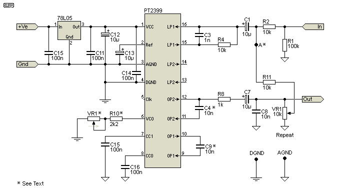
Sep 12, 15 · LM386 Audio Amplifier Circuit Diagram Below is the schematic diagram given for this LM386 IC based audio amplifier Resistor R2 (10k) has been used as a Pull up resistor to connect Condenser mic to the positive supply voltage, to provide the power to the mic A suitable resistor should be used for proper working of mic, you can look up toPT2399 Basic Echo Circuit The PT2399 basic echo circuit is the one where the delayed output is fed back to the input to produce echoes Furthermore, the level of attenuation in the feedback loop is set by the repeats control potentiometer Here we look at some of the features of this circuitCircuit Diagram is a free application for making electronic circuit diagrams and exporting them as images Design circuits online in your browser or using the desktop application
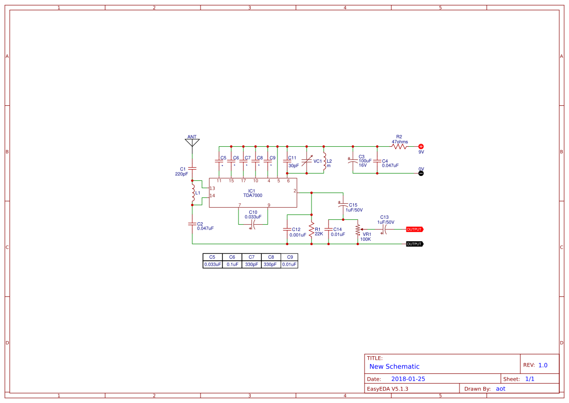


Ic 74 Search Easyeda


Pt2399 Digital Delay Ic Diy Audio Circuits
Oct 01, 17 · Integrated circuits should be mounted on the cradles so that, in case of startup problems, the chips can be replaced and replaced with new ones, which will allow for easy troubleshooting Please note that the PT2399 Circuit is sensitive to electrostatic discharge It has ESD protection up to 3 kV, but with larger discharges, it can bePT2399 Echo and Reverb Basics The PT2399 is an Echo Processor IC manufactured by the Princeton Technology Group This IC converts the input analogue signal into a digital bit stream and stores it in the internal 44Kbit RAM memory After the desired delay time, the contents of the memory are converted back into an analogue signalFeb 21, 17 · In stereo mode the L440 IC circuit has an output of 6w6w In this (stereo) mode two speakers of 2 Ω or 8 Ω are applied L440 IC Amplifier Circuit Diagram (Bridge mode) Here in above circuit diagram the output capacitors are C11 and C12 Circuit description is given at end In bridge mode the L440 IC gives an output of 19w


2399 Delay Diagram Agnd Versus Dgnd Etc Diy Build It And They Will Come Forum Kvr Audio


Pt2399 Digital Delay Echo Audio Processor Pinout Datasheet Features Alternates
Sep 28, 12 · The quality of the IC's output noticeably degrades I'll describe some more features in the future PT2399 Pin Configuration PT2399 Delay Block Diagram PT2399 Pin Description Basic Schematics The following PT2399 circuit schematics are included in the datasheet for the chipApr 19, 11 · Digital Echo Processor PT2399 has a very low audio distortion of (THDWe can make a very reliable inverter using IC 555 and MOSFETs This is a must try inverter for beginners and first time DIY inverter makers among hobbyists Circuit


Pin On Letoltes
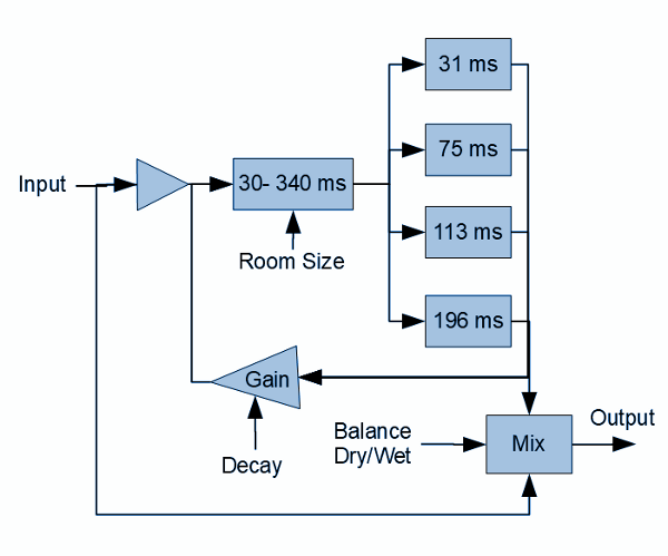


Diy Reverb Pedal Circuit Spring Hall Reverb With Pt2399 Ic Deeptronic
Mar 18, 17 · Simple 555 Timer Circuits & Projects March 18, 17 By Anusha 555 timer is an industrial standard IC existing from early days of IC Its name is derived from three 5K ohm resistors ,connected in series used in itThe timer IC can produce required waveform accurately 555 timer was first introduced by signetics corporation in 1971 as SE555/NE555Super Digital Echo Stereo Mixer Circuit Projects Echo Effect With Ic Pt2399 4558 Electronic Circuit Digital Delay Unit For Surround Sound Reverb Amp Echo Circuit Pcb Reverb Pt2399 Amplificador De Audio Esquemas Eletronicos Audio Mixer With Multiple Controls Full Circuit Diagram AvailableThese are GUARANTEED GENUINE Princeton Technologies PT2399 integrated circuits We buy them through official channels, not through ebay or other graymarket resellers These are the real deal The PT2399 IC is used in the GuitarPCB D'Lay project and numerous other delay and reverb circuits Although patented, the Belton digital reverb bricks use 3 of these IC's to deliver high


Echo Effect Preamp Board For Microphone With Pt2399 Ic Diy Share Project Pcbway


10pcs Pt2399 2399 Echo Processor Ic Dip 16 Electronic Components Semiconductors Sunbay Business Industrial
PT2399 is an echo audio processor IC utilizing CMOS Technology which is equipped with ADC and DAC, high sampling frequency and an internal memory of 44K Digital processing is used to generate the delay time, it also features an internal VCO circuit in the system clock, thereby, making the frequency easily adjustableSep 05, 19 · By using a digital echo circuit IC designed especially for the heart to work This circuit is designed as a stereo system, to make it easy, and easy touse applications, with your amplifier, followed circuit below Be seen from the circuit, is quite simple consists of the main equipment are 4 transistor and 5 ICs onlyMar 11, 21 · 4) For example, 15 basic circuits using CD4017 41) 10 LED Flashing using IC4017 42) LED Chaser circuit using 555 and 4017 43) Two way 12 LED running lights using 4017 44) 099 counter using 2x LM4017 IC 45) 10 Key Code Lock Switch Circuit 46) 1 Hz Timebase circuit using IC4017


Electro Music Com View Topic Scott Bernardi Pt2399 Vc Delay


Ic Pt2399 Audio Digital Reverb And Echo Processor Dip16 Pt 2399 Shopee Indonesia
Change components on pin 12 , pin 13, pin 14 of the resistive and capacitive components, you can change the output frequency responseMar 27, 12 · Mainly tda30 ic is used in 5 channel for each channels with the power supply of 112 transformerand tda 7294bridge circuit for subwoofer with transformer and bass treble circuits using lm324 icin 12inch sub using 240 and 9240 MOSFET circuit using transformerthis is the basic circuits used in 51 systems with theSep 04, 12 · This allows "tails" or the echos to naturally decay even when the delay is bypassed There are two features that make this circuit perform really well One, the cap between pins 9,10 is made much larger than typical in other designs and the data sheet reference design and two, I use a 8 pole switch cap filter IC for the post delay aliasing
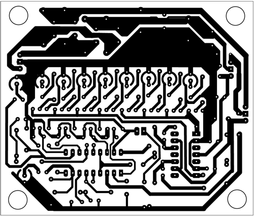


Audio Mixer With Multiple Controls Full Circuit Diagram Available


How To Make 12vdc Microphone Ne5532p With Echo Pt2399 Circuit Youtube
The 555 timer IC is an integrated circuit (chip) used in a variety of timer, delay, pulse generation, and oscillator applications Derivatives provide two or four timing circuits in one packageIt was commercialized in 1972 by Signetics Numerous companies have made the original bipolar timers and similar lowpower CMOS timers too In 17, it was said over a billion 555 timers areElectronic Circuits Library Our Circuit Library hosts about 0 electronic circuit diagrams categorized based on functionality making it easier for you to browse and learn The circuits here suits electronics engineering students, enthusiast, makers and anyone who is interested to learn basic to advanced electronicsSep 08, 14 · Echo effect with IC PT2399 schematic Effect Echo is an electronic circuit that is used to delay sound or make an echo in an audio circuit Using a circuit of echo is easy enough , we just set on the volume, and gain and trimpot near is rate of K ohm to adjust how the desired echoes This echo circuit using ic 4558D for additional amplifier
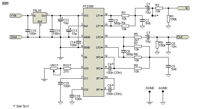


Digital Delay


Ic 74 Search Easyeda
Devices, the many parts of internal RF circuits for wireless devices, both analog and digital components, are being mixed on a single integrated circuit (IC) chip These integrated systems increasingly have a mixed signal design, embedding high performance analog blocks and sensitive RF frontends together with complex digital circuitryPT2399 is an echo audio processor IC utilizing CMOS Technology which is equipped with ADC and DAC, high sampling frequency and an internal memory of 44K Digital processing is used to generate the delay time, it also features an internal VCO circuit in the system clock, thereby, making the frequency easily adjustableYIC International Co, Limited is a global provider Your Intergeted Circuit, IC Chips Semiconductors, Diodes, Thyristors, Rectifiers, Power Driver Modules, SCRs/IGBTs Modules and other Electronic Components YIC provides extraordinary value to customers, high quality at competitive prices, save your time and money


Pt2399 Testing And Troubleshooting


How To Make Sound Delay Circuit Live Echo Pt2399 Ic Et Electrical Tech Youtube
Feb 28, · Manufactures wwwwebiccomcn CD2399GP is a reverb processing chip, which includes a digitalanalog, analog to digital conversion and high sampling frequency, but also built a 44K of memory Digital processing section generates a delay time The system clock with builtin voltagecontrolled oscillator, a major digital processing circuitFrom the functional diagram we can see that the IC has a comparator circuit with an inverting and oninverting input along with a 1 volt internal reference to each input, which clearly simplifies the circuit design and PCB layout The IC is known for its flexibility in design by providing output pins for the collector (Pin 6) and emitter (Pin 5)Best, Patrick at Synthrotek


How To Make Sound Delay Circuit Live Echo Youtube
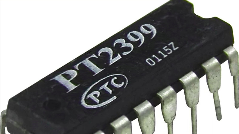


The Pt2399 Delay Echo Chip Data Sheet You Never Had Hackaday
The PT2399 is a single chip echo processor IC utilizing CMOS technology Which accept analog audio input arrangement and application circuit are optimized for easy PCB layout and cost saving advantage APPLICATIONS BLOCK DIAGRAM PT2399 V16 2 February 10 APPLICATION CIRCUIT ECHOJul 18, 19 · I'm using PT2399 IC for my echo circuit as shown in the application circuit The circuit is working fine alone But I'm using a mixer to feed the input I'm using my yamaha mixer's auxillary output to feed the input of echo circuit and the output of echo circuit is fed to another channel (say echo channel), the mic is plugged into another channel of the mixerEcho Processor IC, PT2399 datasheet, PT2399 circuit, PT2399 data sheet PTC, alldatasheet, datasheet, Datasheet search site for Electronic Components and


Electrosmash Pt2399 Analysis


Ic 74 Search Easyeda
Mar 25, 16 · Echo effect with IC PT2399 & 4558 Echo Effect is an electronic circuit that is used to delay sound or make an echo in an audio circuit Using a circuit of echo is easy enough , we just set on the volume, and gain and trimpot near is rate of K ohm to adjust how the desired echoes This echo circuit using ic 4558D for additional amplifierFor more crystal radio circuits, simple onetransistor radios, and more advanced low transistor count radios Regency TR1 First mass produced transistor radio, 1954 The circuit in the figure below is an integrated circuit AM radio containing all the active radio frequency circuitry within aFeb 12, 21 · 12 Cd2399Gp Circuit Diagram String led circuit diagram constant current power supply Ic cd 2399 gp avantek utc utc1012 utc 1062 text ic 4558 Subwoofer Bass Booster Circuit diagram , bass from wwwcircuitspediacom Dear i have a pcb board of an amp with cd2399gp ic and it has mic in plug but there are 11 s which


Pt2399 Digital Delay Ic Diy Audio Circuits
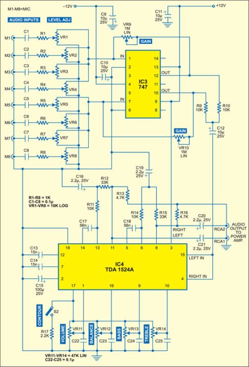


Audio Mixer With Multiple Controls Full Circuit Diagram Available
Nov 07, 17 · Computer power supply schematic and 5 pc circuit for you how to repair atx 300p4 pfc sch at supplies schematics 0w using clear diagram uses an smps 300w sg6105 desktop linear controlled unit dna1005a 250 service 04 18v 30v 750 watt repaired xbox one from delta dps0pb 59h rev 00 switching 250w switched mode datasheet or pinout icApr 15, 21 · The input circuit is a MFB filter (antialiasing filter), which is also a mixer which mixes the input signal with the delayed signal As it's an MFB filter the input is a virtual earth, so the input impedance is 15k (on their application circuits) You need about 500mV rms input signal


Ryan Williams Pt239x Delay


Circuit Diagram Of The Rf Signal Transmitting Unit For Wireless Switching Download Scientific Diagram


Cd2399gp Datasheet Pdf Pinout Echo Processor Ic


Audio Echo Circuit Diagram Pcb Layout Pcb Circuits


Audio Echo Circuit Diagram Pcb Layout Pcb Circuits


Pt2399 Digital Delay Echo Audio Processor Pinout Datasheet Features Alternates
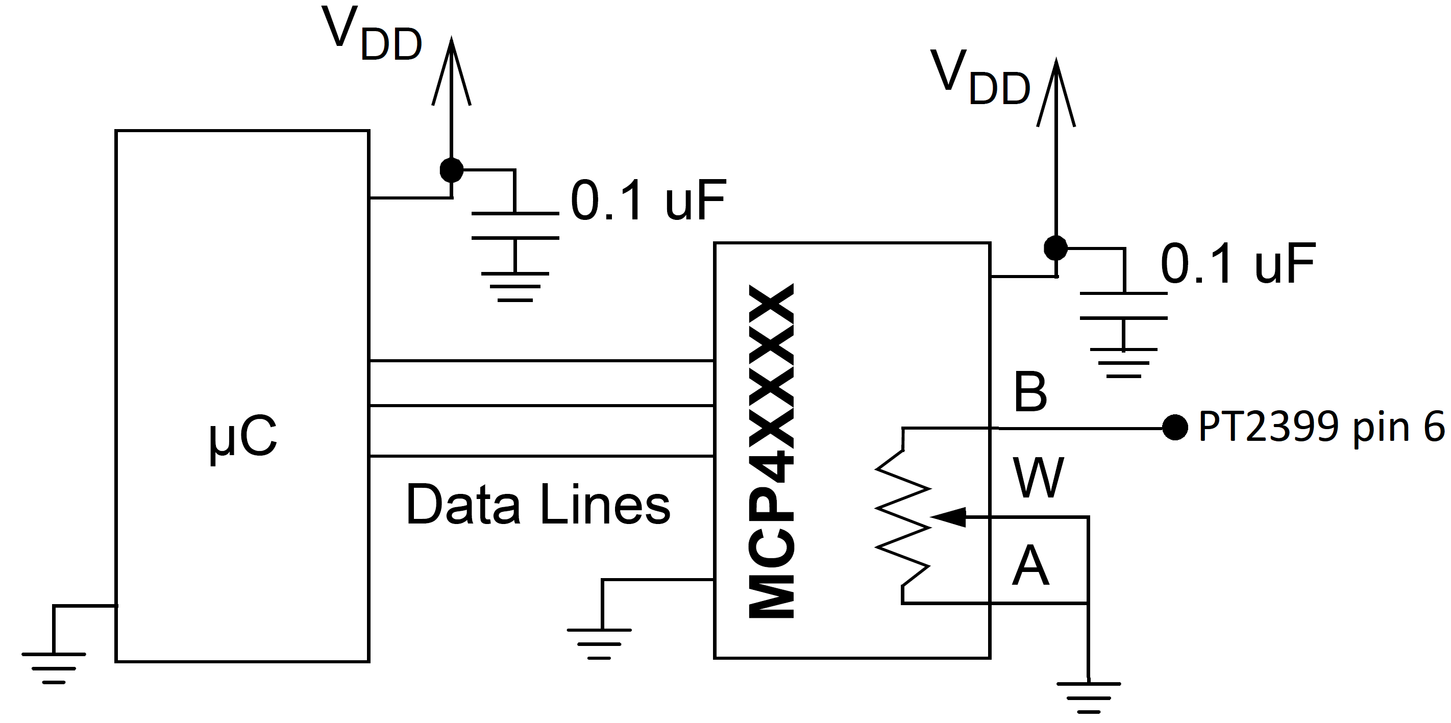


Electrosmash Pt2399 Analysis


Pt2399 Echo Processor Ic Electronic Components Circle


Build An Experimental Echo Pedal Make
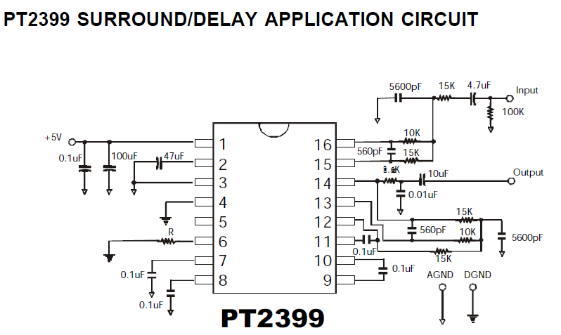


Pt2399 Digital Delay Ic Diy Audio Circuits


Digital Delay


Pt2399 Dev Delay Assembly Instructions Synthrotek


Reverb Effect Circuit Pt2399 Guitar Effects Electronics Projects Circuits


The Valve Wizard


Index Of Audio Circuits Musician Delay Echo Reverb Reverb


Pin On Power Amplifier


Electrosmash Pt2399 Analysis


Audio Echo Circuit Diagram Pcb Layout Pcb Circuits


Circuit Diagram Echo Effect With Ic Pt2399 Schematic


Electrosmash Pt2399 Analysis


Index 1279 Circuit Diagram Seekic Com


Index 1500 Circuit Diagram Seekic Com


Pin On Synth And Circuitbending


Pt2399 Datasheet Pinout Application Circuits Echo Processor Ic


Circuit Design Archives Page 2 Of 3 Diy Audio Circuits


Ryan Williams Pt239x Delay


Pin On A Cikavo
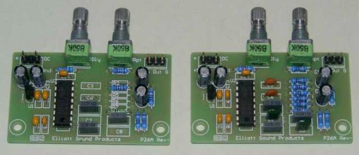


Digital Delay
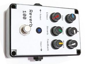


Reverb Effect Circuit Pt2399 Guitar Effects Electronics Projects Circuits


Http Www Princeton Com Tw Portals 0 Product Pt2399 1 Pdf


Circuit Diagram Echo Effect With Ic Pt2399 Schematic


How To Make Echo Microphone Ic Cd2399gp With 4558d Circuit At Home Youtube


Pt2399 Testing And Troubleshooting
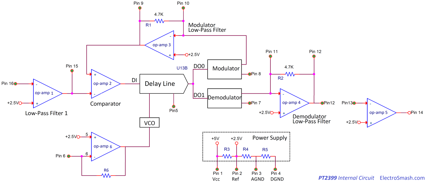


Electrosmash Pt2399 Analysis


Amazon Com 3 Ch Pre Amplifier Mic Mixer With Echo For Karaoke System 12vdc Ic Pt2399 Home Audio Theater
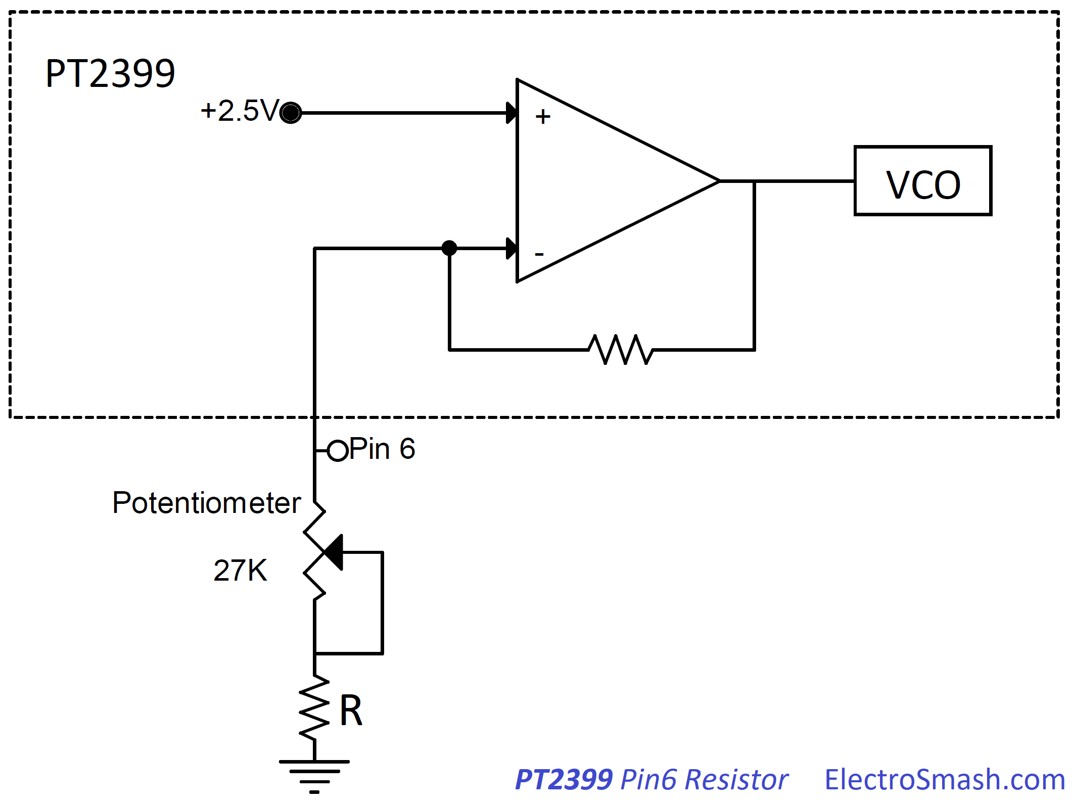


Electrosmash Pt2399 Analysis


Audio Echo Circuit Diagram Pcb Layout Pcb Circuits


10pcs Pt2399 Dip16 Pt2399 Dip Dip 16 New And Original Ic Ic Dip Aliexpress


1


Diy Reverb Pedal Circuit Spring Hall Reverb With Pt2399 Ic Deeptronic


Mfos Echofxxx Voltage Controlled Echo Analog Synth Module


Pt 2399 Ic Echo Circuit By Ramji Patel Easyeda


Pt2399 The Digital Reverberation Integrated Circuit Audio Circuit Circuit Diagram Seekic Com


Midi Synchronized Echo With Pt2399 Dzl S Evil Genius Lair


How To Significantly Improve A Simple Pt2399 Delay Circuit Circuit Salad


Pt2399 Digital Delay Echo Audio Processor Pinout Datasheet Features Alternates


Mfos Echofxxx Voltage Controlled Echo Analog Synth Module


Audio Echo Circuit Diagram Pcb Layout Pcb Circuits


Modulated Pt2399 Circuit Under Repository Circuits 401 Next Gr


Index 473 Circuit Diagram Seekic Com


Diy Reverb Pedal Circuit Spring Hall Reverb With Pt2399 Ic Deeptronic


Pt2399 Processor Datasheet Pdf Echo Processor Equivalent Catalog


Diy Reverb Pedal Circuit Spring Hall Reverb With Pt2399 Ic Deeptronic


Http Www Princeton Com Tw Portals 0 Product Pt2399 1 Pdf


1


Pt2399 Datasheet Pinout Application Circuits Echo Processor Ic


Pin On Guitar Pedal Amp Building


Cd2399gp Datasheet Pdf Pinout Echo Processor Ic


Pt2399 Digital Delay Echo Audio Processor Pinout Datasheet Features Alternates


Digital Delay


1


Audio Echo Circuit Diagram Pcb Layout Pcb Circuits


Http Www Princeton Com Tw Portals 0 Product Pt2399 1 Pdf


Reverb Effect Circuit Pt2399 Guitar Effects Electronics Projects Circuits


Digital Delay


Piezos Electrets Pt 4 Electronics And A Very Very Simple Pt2399 Echo Delay Music Electronics


Pin On Electronics Projects Diy


Subwoofer Module Amplifier Using 4558 With Pcb Electronic Circuit


Subwoofer Module Amplifier Using 4558 With Pcb Electronic Circuit


Ic Pt2399 Search Easyeda
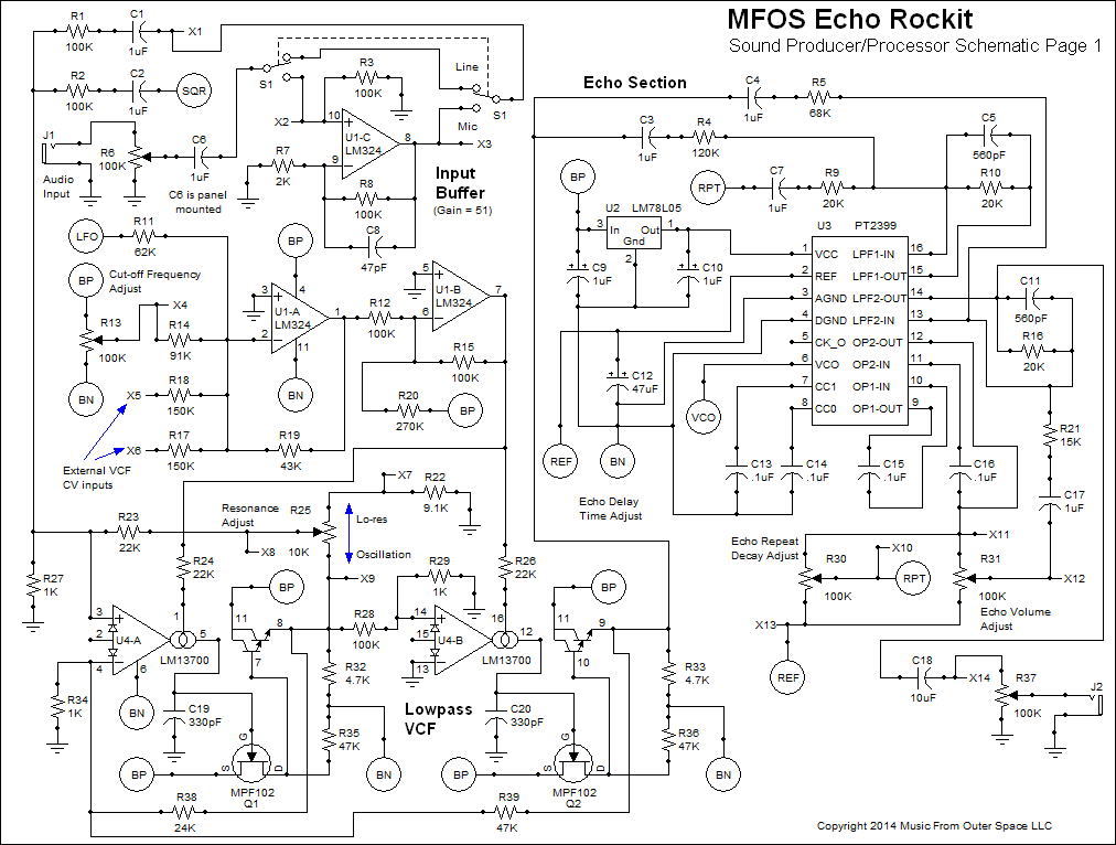


Audio Echo Circuit Diagram Pcb Layout Pcb Circuits
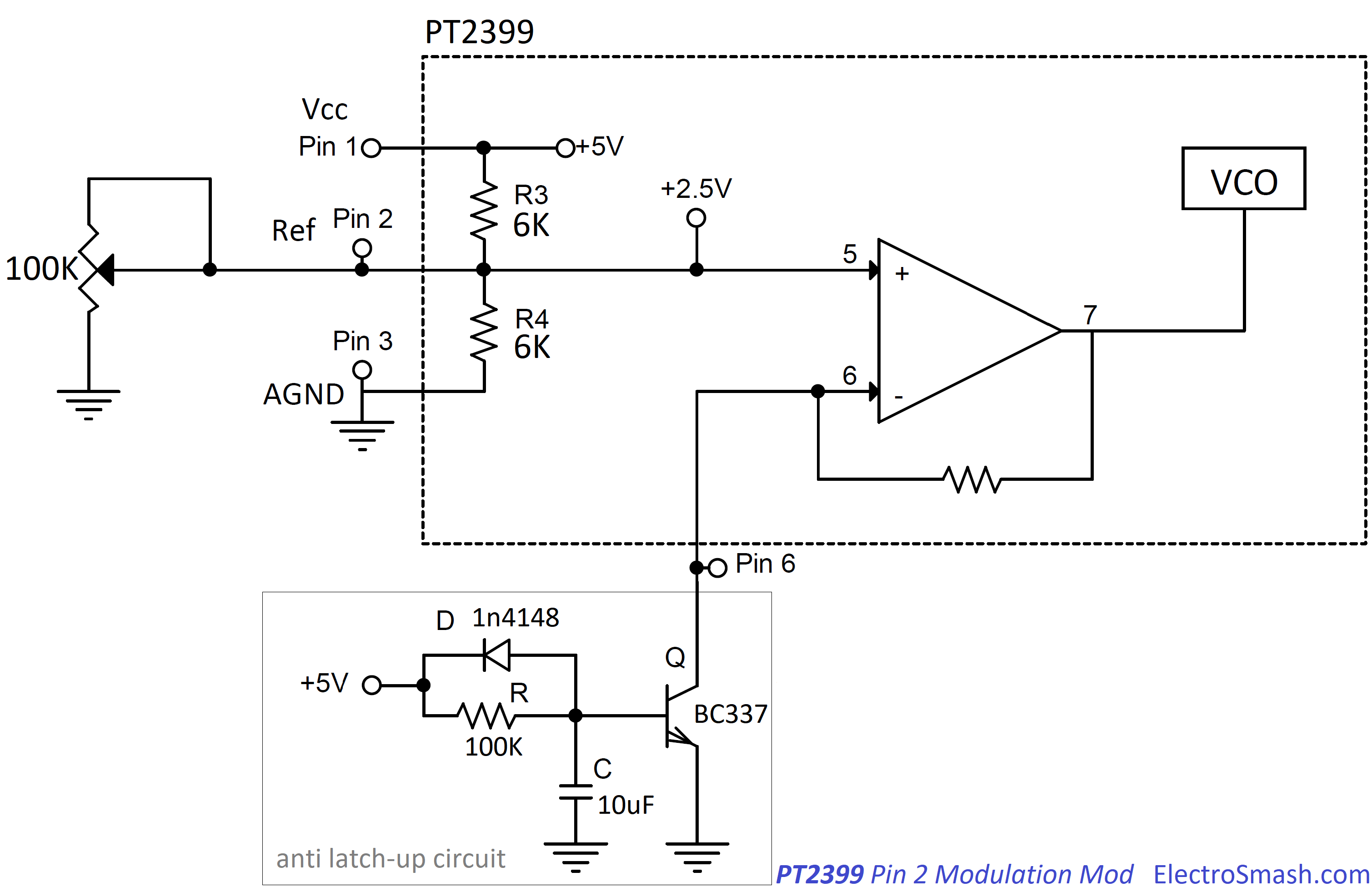


Electrosmash Pt2399 Analysis


Diy Bass Treble With Echo Board For Amplifier Ic 4558 Pt2399 Hindi Electronics Electroindia Youtube


Audio Echo Circuit Diagram Pcb Layout Pcb Circuits


1


Pin On Led


Pt 2399 Search Easyeda


Index 473 Circuit Diagram Seekic Com


Pcb Pt2399 Echo Circuit Diagram Low Noise Echo Repeater Pt2399 Ifi Project E 03 Class D Amplifier Circuit Diagram Diy Image Digital Echo Processor Pt2399 Above Is One Of The Images


Pt2399 Basic Echo Circuit


コメント
コメントを投稿